Spring 2008

ME218C
The Guitar
The Guitar
Overview:
Design paradigm:
Keep it esthetically pleasing, simple, clean, and rock-stiley.
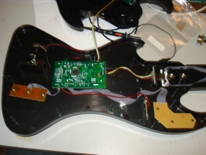
We started out with a Rock Band Guitar controller we got for free because it was broken, gutted all the electronics, added a xBEE radio and a few circuits, and put it all back together. Two PICs and a Radio. Glorious.
Operating Instructions:
Insert batteries and power-up:
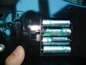
Flip the helm over and on the backside and put 4 AA batteries in your guitar. Turn the guitar on by flipping the power switch next to the batteries. If at any time you want to reset your controller, simply cycle this switch.
iButton pairing:
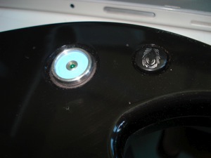
On reset, the Helm waits for an iButton. The green LED in the iButton reader will turn off once you have touched an iButton to the helm and the iButton code was correctly read. Touch the same iButton to a Craft, and they will pair. Notice how your craft’s ID is displayed in binary on the 7’th, 9’th and 12’th frets :) LSB is on the right, from the users viewpoint. Everyone else just has to bitwise flop.
Team affiliation:
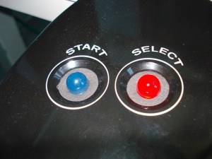
Either the large BLUE or RED LED will now turn on indicating your team affiliation. While playing game, the LED that blinks indicates the active base. If you are on the blue team and the blue base is active, the RED LED will be off and the BLUE LED will blink. If you are on the blue team and the red base is active, the BLUE LED will be on and the RED LED will blink. Simple, and esthetically pleasing.
Gameplay:
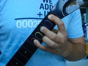
Your helm has 5 frets, fret 1 being the furthest from the body of the guitar, a picking input for strumming, a whammy bar, and a rock-out-tilt sensor.
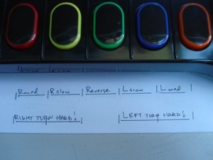
To control your speed, strum! If you want to go backwards, push the 3’rd fret, the fret in the middle, while strumming.
To control your direction, or turn in place, you have 3 turning rates to choose from, and two directions. To turn left slowly, push the 2’nd fret, the one just to the left of the middle fret. To turn left a little quicker, push the 1’st fret, the one on the far left. To turn left a the fastest rate, push both the 1’st and the 2’nd fret. Similarly to turn right, push the 4’th, 5’th, or both the 4’th and the 5’th, in ascending order of turning rate. If you are strumming while you are turning, the craft will move forward or backward. If you don’t strum, the craft will turn in place.
To squirt water, push the whammy bar towards the guitar. The further you dip down into those sweetly flattened notes, the further your craft will squirt water.
Specials!
For the first special, play a 9’th chord by pressing the 1’st, 3’rd and 5’th frets at the same time. This is one of the richest rock chords you can play, something about the 5’th of a 5’th just makes your bones shiver. If you hear one, you'll know what I’m talking about ;) Until then, the duck will probably spin in circles and squirt water, celebrating your musical prowess.
For the second special, power up! By tilting the guitar toward the sky, not only will the women faint and the men salute you, but the duck just might let out a quack or two...
Oh no! Not a Stand-Down! Remember not to break the rules, or let an enemy craft bump you. In the event that the Admirals issue your craft a Stand-Down, your craft will stop all its actions and your guitar will vibrate in disapproval. This is almost as bad as being boo-d off the stage, but at-least in this case you can resume rocking out after 10 seconds of shame.
The Gory Details:
The Power Electronics:
To power the guitar, we used the following circuit.
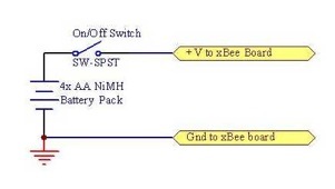
The guitar should last for at-least 8 hours of operation with just 4 AA batteries. We recommend NiMH just to be sure.
2 PICs and an xBEE radio:
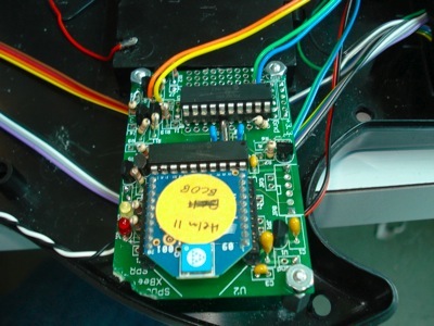
Our microprocessing and radio communication was managed by 2 PIC16F690s and one xBEE radio.
(Check out our downloads pages to see the data sheets for these components)
We used a modified version of the xBEE radio board, adding a second PIC and re-allocating pins by changing the peripheral circuitry. All the inputs from the user, the transmission packets to be sent to the xBEE, and the stand-down buzzer are handled by the Master Helm PIC, or mHelm PIC. The team affiliation LEDs and craft ID fret dot LEDs are controlled by the Dummy Helm PIC, or dHelm PIC.
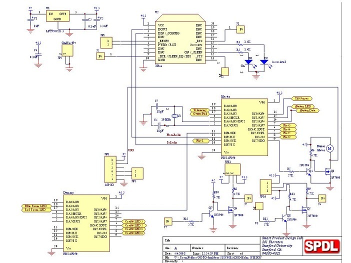
And without a pin to spare, at-least on the mHelm:
;;;;;;;;;;;;;;;;;;;;;;;;;;;;;;;;;;;;;;;;;;;
;; Pin Diagram for Master Helm PIC16F690
;------------------------------------------
; Pin# Desig Use
;------------------------------------------
;| 1 Vdd +5V
;| 2 OSC1 ext. XTL resonator 10MHz
;| 3 OSC2 ext. XTL resonator 10MHz
;| 4 RA3 MSTR CLEAR
;| 5 RC6 FretButton2
;| 6 RC5 FretButton5
;| 7 RC4 FretButton4
;| 8 RC3 FretButton3
;| 9 RC7(SDO) Stand Down Buzzer
;| 10 TX EUSART transmit output
;| 11 RB6 FretButton1
;| 12 RX EUSART receive input
;| 13 RB4 Team_Affiliation to dHelm
;| 14 RC2 iButton
;| 15 RC1
;| 16 RC0 Tilt Sensor
;| 17 RA2 Picking Speed
;| 18 RA1 Whammy Bar
;| 19 RA0 Testing Pin
;| 20 Vss GND
;;;;;;;;;;;;;;;;;;;;;;;;;;;;;;;;;;;;;;;;;;;
;;;;;;;;;;;;;;;;;;;;;;;;;;;;;;;;;;;;;;;;;;;
;; Pin Diagram for Dummy Helm PIC16F690
;------------------------------------------
; Pin# Desig Use
;------------------------------------------
;| 1 Vdd +5V
;| 2 OSC1 ext. XTL resonator 10MHz
;| 3 OSC2 ext. XTL resonator 10MHz
;| 4 RA3 MSTR CLEAR
;| 5 RC6 CraftID_LED_4
;| 6 RC5 CraftID_LED_1
;| 7 RC4 CraftID_LED_2
;| 8 RC3 CraftID_LED_3
;| 9 RC7 Team_Affiliation from mHelm
;| 10 TX EUSART transmit output (disconnected)
;| 11 RB6
;| 12 RX EUSART receive input
;| 13 RB4 (SDI)
;| 14 RC2
;| 15 RC1
;| 16 RC0 iButton LED
;| 17 RA2 Red LED indicator
;| 18 RA1 Blue LED indicator
;| 19 RA0 Test Pin
;| 20 Vss GND
;;;;;;;;;;;;;;;;;;;;;;;;;;;;;;;;;;;;;;;;;;;
Team Affiliation and Craft ID:
Once the iButton is read correctly, the mHelm PIC communicates team affiliation to the dHelm PIC via the Team_Affiliation line. The dHelm waits until it hears a craft match packet from a craft to display team affiliation on the colored LEDs.
The signals from the PIC were converted to 5V logic to ensure enough voltage for these larger LEDs.
The dHelm also records the craft ID of the craft that responds with a Matched packet, and displays the ID on the four fret dot LEDs, LSB on the right from the viewpoint of the user. Because the smaller green LEDs had a much smaller voltage drop, we used 3.3 volt logic to save power, and ran the signals straight through 2n7000 transistors.
Gameplay inputs:
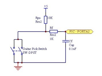
The pick input:
The original electronics board for the guitar had two nice normal open switches mounted on it, one for an upward pick and one for a downward pick. The action of picking rotates the pick sensor until it closes one of these switches. To use these, we simply un-soldered the signal lines to the original electronics board, and put our own de-bounce and sensing circuit in its place. We weren’t concerned with discerning an up-strum from a down-strum, so both switches closed the same signal line. We used the original circuit board as a structural element, holding the switches in the correct location.
To measure strum rate and create a speed nibble, we set up an overflow counter on Timer0 and used this to keep track of the the time delay between picks. The pick input and overflow counter were handled in interrupts as shown below, creating a PICK_SPEED variable later used to create the Nav Byte.
;;;;;;;;;;;;;;;;;;;;;;;;;;;;;;;;;;;;;;;;;;;;;;;;;;;;;;;;;;;;;;;;;;;;;;;;;;;;;;;;;;;;;;;;;;;
PICK_INTERRUPT_RESPONSE:
BCFINTCON,RABIF; clear the interrupt flag
BTFSCPICK; if the Pick input is LO, respond
GOTOEND_INTERRUPT_RESPONSE_ROUTINE; Otherwise get out of here!
MOVLW0x02
SUBWFPICK_DELAY,F; subtract 2 for a range from 0 to 15
BTFSSSTATUS,C; Check not borrow bit, if no borrow, this is 1
CLRFPICK_DELAY; if there was a borrow, store W to 0
MOVFPICK_DELAY,W
RRFPICK_DELAY,F; Bit Shift PICK_DELAY Right for a range of 0 to 7 (devide by 2)
BCFPICK_DELAY,7; Make sure no carry bit came in here.
MOVFPICK_DELAY,W
BTFSCFRET_3; if the reverse action is pressed, you're done.
SUBLW0x0F; if you want to go forward,
; subtract W from 0x0F and this becomes your speed.
; store this in PICK_SPEED for later reference in CREATE_NAV_BYTE
MOVWFPICK_SPEED
MOVFTMR0_BYTE01,W; Store current time for next pick calculation
MOVWFLAST_PICK_TIME;
GOTOEND_INTERRUPT_RESPONSE_ROUTINE; and get out!
;;;;;;;;;;;;;;;;;;;;;;;;;;;;;;;;;;;;;;;;;;;;;;;;;;;;;;;;;;;;;;;;;;;;;;;;;;;;;;;;;;;;;;;;;;;
TIMER0_INTERRUPT_RESPONSE:
BCFINTCON,T0IF; clear the interrupt flag
; insert something here for the craft to have another level of overflow. - check if it is 0xFF and add one to TMR0BYTE02
; if PICK_DELAY = 17 => INCF LAST_PICK_TIME
MOVFLAST_PICK_TIME,W; TMR0_BYTE01 - LAST_PICK_TIME = PICK_DELAY
SUBWFTMR0_BYTE01,W; *,0 stores in W
MOVWFPICK_DELAY; this should be a range from 4 to 19
MOVLW0x11; load in d'17' to compare to
XORWFPICK_DELAY,W; compare this with number of actual reads
BTFSSSTATUS,Z; check if they match (Z bit set)
GOTOALMOST_DONE_WITH_TIMER0_INTERRUPT_RESPONSE
INCFLAST_PICK_TIME; if they match, increment LAST_PICK_TIME
; by doing this, the calculation of PICK_DELAY
; will remain 15 until you pick twice rapidly.
MOVLW0x08; and set the speed to 0
MOVWFPICK_SPEED
ALMOST_DONE_WITH_TIMER0_INTERRUPT_RESPONSE:
INCFTMR0_BYTE01; increment the overflow counter, our More Significant timer byte.
; check if timer0-01 overflows and if so, increment timer0-02
MOVLW0x00
XORWFTMR0_BYTE01,W
BTFSCSTATUS,Z
INCFTMR0_BYTE02
GOTOEND_INTERRUPT_RESPONSE_ROUTINE; and get out!
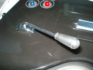
The frets:
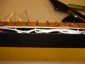
This image shows the backside of the fret button board. We used the buttons from the original guitar but soldered our own signal wires and used our own 10k pull-up resistors. The buttons are normal open.
To translate these button pushes into a direction nibble we used the following code.
CREATE_NAV_BYTE:
; This grabs the picking speed from the Picking Interrupt, puts this into TX_NAV_DATA, and checks the frets for direction inputs.
; If a chord is being played(135 for Special 1), it uses the same direction inputs as whatever it used before the chord was played.
; if FRET_1, FRET_3, and FRET_5 are low (indicating special 1)
bankselPORTA
;CHANGE
CLRFTX_NAV_DATA;reset NAV_DATA to start off
MOVFPICK_SPEED,W
MOVWFTX_NAV_DATA
BSFTX_NAV_DATA,7; start it out with no turning by setting 1000
BTFSSFRET_1; check if fret 1 is pressed
CALLSUBTRACT_5_FROM_TX_NAV_DATA_DIRECTION; if so, subtract 5 from DIR
BTFSSFRET_2
CALLSUBTRACT_3_FROM_TX_NAV_DATA_DIRECTION
BTFSSFRET_4
CALLADD_2_TO_TX_NAV_DATA_DIRECTION
BTFSSFRET_5
CALLADD_5_TO_TX_NAV_DATA_DIRECTION
RETURN
SUBTRACT_5_FROM_TX_NAV_DATA_DIRECTION:
MOVLW0x50
SUBWFTX_NAV_DATA,F
RETURN
SUBTRACT_3_FROM_TX_NAV_DATA_DIRECTION:
MOVLW0x30
SUBWFTX_NAV_DATA,F
RETURN
ADD_2_TO_TX_NAV_DATA_DIRECTION:
MOVLW0x20
ADDWFTX_NAV_DATA,F
RETURN
ADD_5_TO_TX_NAV_DATA_DIRECTION:
MOVLW0x50
ADDWFTX_NAV_DATA,F
RETURN
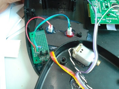
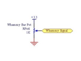
Whammy bar Water Pump control:
We used the original 10k Whammy pot, which gave an analog input ranging from 1.15 to 3.3 volts, 3.3 being fully depressed.
Rock-out tilt sensing:
My favorite part of the original design of the guitar controller was the tilt sensor. Not only was it obviously incredibly cheap to manufacture, but it worked universally for left handed and right handed users alike. This was implemented by two balls rolling within cap-like cans, mounted 45 degrees from horizontal, one facing the sky and one facing the ground. When the guitar is pointed upwards, both balls roll to the bottom of the can and short the signal wire. Otherwise the signal is open. One 10k pull-up resistor and probably less than 1c of hardware and you can sense tilts!
You can go to our downloads page to check our full code listing for the guitar.
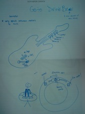
the Helm Exploded.
a View of its Guts.
Driving the Duckie.