Spring 2008

ME218C
Everything In-between
Overview:
Our overall communications are broken up into two main sections -- iButton serial reading and XBee RF communications. Read on for more background and info about how we implemented these two elements.
iButton Pairing:
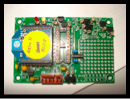
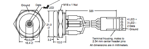
The iButton is a compact, user-friendly data transfer device. It is capable of reading in a range of sensor inputs, but we used it only for serial number reading. Each iButton is hard-coded with a unique serial number. The matching reader, pictured below, can read this number into you micro-controller. When a helm and a craft have read in the same iButton serial number, they can match numbers and pair for directed communications.
Reading in an iButton is simple from the user’s side. A green LED illuminates to indicate that the iButton is ready to be read. Then all you have to do is press the iButton into the reader, making good contact for less the a second; it will read in the serial number and turn off the LED to indicate a successful read.
Implementing this seemless interface is a bit more complicated. Data is both transferred and received to/from the reader through one DATA pin. Communicating with the reader boils down to a well timed dance of voltages, switching the µC DATA pin back and forth from input to output. Check out this document describing the reading procedure. This required accurately calibrated timers on the PIC in the micro-second range. You can see this reading sequence implemented in our code listing. It was a universal section that we used unchanged on each PIC.
Zooming out to a higher level, we can look at how the code was organized. On start-up, both the Craft and Helm would initialize to waiting for the iButton, turning on the green reader LED to indicate this to the user. The master PIC would then loop, scanning the data line in search of an iButton. Once an iButton was detected, interrupts would temporally be turned off so as not to interfere with timing and the iButton would be read in. We required five identical, non-zero serial numbers to be read in a row, to make sure we got an accurate reading. Once read, interrupts were re-enabled, the green indicator LED was turned off, and the PIC proceeded to the next state in code, to match with the appropriate Craft/Helm. This was a highly reliable and speedy process that left us with the simple user experience described above – you should need a degree in electrical engineering to drive a duck with a guitar.
XBee RF Modules: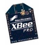
The class was provided with XBee RF modules for our wireless communication. These are low-cost (~50$), low-power (~50mA @ 3.3V) radio frequency transmitter/receivers. They operate at the 2.4GHz frequency range and have an ample 30m range in our typical “urban” environment.
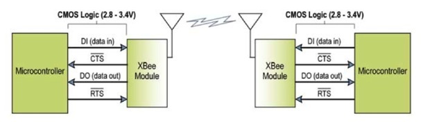
Communicating wirelessly through the XBee modules was happily an almost transparent process. By default, the module acts as a serial line replacement – this means all serial line transmissions received from a micro-controller are automatically transformed into an RF message and any received RF message gets transformed back by the XBee to the serial receive line of the µC. The XBee was even able to automatically check the airwaves to avoid overlapping transmissions, keeping another critical feature functional but transparent. Below is a diagram for this system of transparent RF transmission passing:
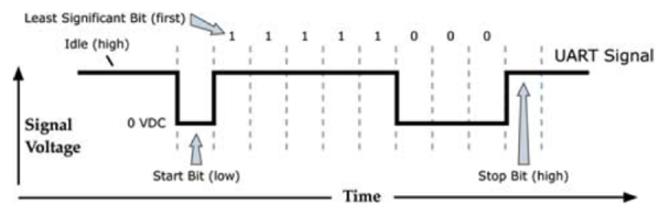
We used the asynchronous serial line, codenamed EUSART on the PIC, to talk with our XBee modules. Individual bytes are transmitted and received based on the basic protocol picture below.
In order to pass the XBee a complete message, i.e. some meaningful collection of bytes, there is another simple protocol to stick to. The first byte passed is a start byte, 0x7E, followed by two bytes indicating the length of the message, then followed by your data, and concluding with a calculated checksum byte. More info on this can be found in the XBee data sheet in our downloads section.
Communications Protocol:
The next hurdle beyond simply sending wireless transmissions between the XBee modules was to come up with a standardized communications protocol for the entire class to follow. If each team passed information in the same format between the helm and the craft, then ideally any helm would be able to control any craft. This also served to create a standard format for the Admiral transmissions. A group of students, made up of one representative from each team, met over the first two weeks of the project to create this protocol. They came up with a detailed Communications Protocol, available on our downloads page, with the following structure as the standard for each XBee data packet:
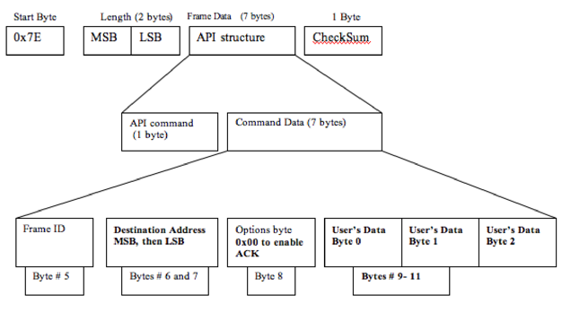
The meat of the packet (or equivalent, tasty vegetarian option) is the three “User’s Data” bytes. The first is the Header byte, which communicates the type of message that is being sent/received – this could fall under classifications such as a Craft message, Admiral command, or Helm Navigation command. The next two bytes were the actual data for the particular message – for example, whether the Admiral is sending a Start Game or a Stand Down command.
The majority of messages passed during a game were Navigation commands, messages from the Helm telling the Craft what to do. Byte 1, the “Navigation Byte,” was split in half: the first nibble communicated steering direction and the second nibble described craft speed. At four bits each, there was a range of 16 values, and each variable centered around a value of 8. For direction, this center value of 0x8* represented straight forward, while 0x0* was an extreme left and 0xF* was an extreme right. For speed, 0x*8 was zero speed, while lower values were reverse down to a max reverse of 0x*0 and 0x*F was full speed ahead. Again, you can check out the Communications Protocol for a clear and in depth description of these details.
EUSART Asynchronous Serial Communications:
The final challenge was how to pass and receive these data packets in code. We were using only PIC’s, so everything was done in Assembly Code (yeah!). We ended up implementing both our asynchronous serial transmission and reception through interrupts. This allowed us to process individual bytes quickly without blocking other processes and messages. The interrupt driven processes for both the transmit and receive lines are described below. The code was generalized to work universally on each PIC that we used.
Receiving an XBee message:
Whenever a new byte was received into the EUSART receive register, an interrupt service routine (ISR) would be triggered to process that byte. Over the span of receiving a full data packet, each byte would be saved into a corresponding file register, and at the end, a flag would be set indicating that a new packet had been received.
This process started of with the RX_INDEX, a variable that kept track of which byte we were currently reading in. While the index was set at zero, we would only check if the incoming byte was a Start byte. If it was, a new packet was incoming, so the index was incremented to begin saving the following bytes. This was done through indirect registering. The file registers for all 12 bytes in a received packet were defined in a block, from 0x60 to 0x6B, beginning with the Start byte. Thus, to save the current received byte to the correct register, we would set the indirect register address to the Start byte address plus the current index – for example to save the 3rd incoming byte, we would load it into the address 0x60 + 0x02 0x62 (recall that the addresses and index are zero indexed). So simple! The following is the code for this interrupt service routine:
;;;;;;;;;;;;;;;;;;;;;;;;;;;;;;;;;;;;;;;;;;;;;;;;;;;;;;;;;;;;;;;;;;;;;;;;;;;;;;;;;;;;;;;;;;;
RECEIVE_INTERRUPT_RESPONSE:
; Handles a full receive register and stores information into the packets
CHECK_RX_BYTE:
banksel RX_INDEX
MOVFRX_INDEX,W
BTFSSSTATUS,Z; check to see if you are at the start byte
GOTOREAD_NEXT_BYTE
GOTOCHECK_FOR_START_BYTE
CHECK_FOR_START_BYTE:
MOVFRCREG,W; else, load Receive Register into W
MOVWFRX_START_BYTE
XORLWSTART_BYTE; compare with start byte
BTFSSSTATUS,Z; check if it matches start byte
GOTOEND_INTERRUPT_RESPONSE_ROUTINE; now GIT 'ER OUT!
INCFRX_INDEX,F; if it does, then increment the index
GOTOEND_INTERRUPT_RESPONSE_ROUTINE; now GIT 'ER OUT!
READ_NEXT_BYTE:
MOVLWRX_START_BYTE;load in address of Start Byte (other bytes follow in address order)
ADDWFRX_INDEX,W;add current index to this initial register address
MOVWFFSR;load indexed address to indirect register address
MOVFRCREG,W;load Receive Register message to W
MOVWFINDF;load message byte into register pointed to by indirect register
INCFRX_INDEX,F; Increment index
; check to see if done with packet
MOVLWd'12'; end of packet (12 bytes total, start byte is 0)
XORWFRX_INDEX,W; compare current index to final byte index
BTFSSSTATUS,Z; check to see if they match
GOTOEND_INTERRUPT_RESPONSE_ROUTINE; now GIT 'ER OUT!
CLRFRX_INDEX; Restart the index (so I am now looking for a start bye next)
BSFRECEIVED_PACKET_FLAG; Set flag to indicate that there is an unread message
;Disable receive interrupt until I deal with this message
bankselPIE1
BCFPIE1,RCIE
bankselPIR1
GOTOEND_INTERRUPT_RESPONSE_ROUTINE; now GIT 'ER OUT!
;;;;;;;;;;;;;;;;;;;;;;;;;;;;;;;;;;;;;;;;;;;;;;;;;;;;;;;;;;;;;;;;;;;;;;;;;;;;;;;;;;;;;;;;;;;
Once we had received a full packet of 12 bytes, the ISR would reset the index back to zero and set the RECEIVED_PACKET_FLAG, indicating that there was a new message to be processed. All of this happened discretely in the background, without any nasty blocking code. In each State of our state machine, we would check this received flag, and if it was high, we would go in and process the message. Processing meant reading through the saved bytes to see the type and content of the message and responding accordingly – responding could literally mean sending a response message if necessary or it could be actuating a motor or changing some LED’s. You can explore the full receiving code on our downloads page.
Transmitting an XBee message:
The interrupt driven routine for transmitting an XBee message worked in a similar manner to the receiving, with a few added complexities. When a message needed to be sent, all the appropriate bytes for the data packet were saved into their corresponding file registers – again these registers were defined in a block like the receiver registers, from 0x50-0x5B, so that indirect registering could be used. With the desired packet loaded, the TRANSMISSION_IN_PROGRESS_FLAG was set and the transmission interrupt was enabled. This interrupt was driven by the EUSART transmit buffer. Whenever this buffer was empty, it meant that a new transmission byte could be accepted, and thus the corresponding interrupt service routine was triggered. This ISR would load in the next byte into the transmit buffer, based on an indirect registering system just like the one described above for the receive side – the byte address was calculated as the Start Byte address plus the current transmit index. When the final, 12th byte was loaded in to be transmitted, the index was reset to zero, the TRANSMISSION_IN_PROGRESS_FLAG was cleared, and the transmit interrupt was disabled to turn off this automatic transmission process. The following is the complete code for this transmission ISR.
;;;;;;;;;;;;;;;;;;;;;;;;;;;;;;;;;;;;;;;;;;;;;;;;;;;;;;;;;;;;;;;;;;;;;;;;;;;;;;;;;;;;;;;;;;;
TRANSMIT_INTERRUPT_RESPONSE:
bankselPIE1
BTFSSPIE1,TXIE;check if the interrupt is enabled...do we have more data to send?
GOTOEND_INTERRUPT_RESPONSE_ROUTINE;if not set, no data to send, so GIT 'ER OUT!
bankselTX_INDEX
; indirect addressing using FSR and INDF.
; (TX_START_BYTE marks beginning of table in Universable_Variable_Defines.h)
MOVLWTX_START_BYTE;address of start byte
ADDWFTX_INDEX,W;add current index to address
MOVWFFSR;load indexed address to indirect register address
;send loaded message
MOVFINDF,W; load message to register in indirect register
MOVWFTXREG; load W to transmit register to send
INCFTX_INDEX,F;increment the index
; check to see if done with packet
MOVLWd'12'; end of packet (12 bytes total, start byte is 0)
XORWFTX_INDEX,W; compare current index to final byte index
BTFSSSTATUS,Z; check to see if they match
GOTOEND_INTERRUPT_RESPONSE_ROUTINE; now GIT 'ER OUT!
CLRFTX_INDEX; Restart the index (so I am now looking for a start byte next)
bankselPIE1
BCFPIE1,TXIE; Disable transmit interrupt
bankselPIR1
BCFTRANSMISSION_IN_PROGRESS_FLAG ;Clear the transmission flag....
;(we're done transmitting a packet)
GOTOEND_INTERRUPT_RESPONSE_ROUTINE; now GIT 'ER OUT!
;;;;;;;;;;;;;;;;;;;;;;;;;;;;;;;;;;;;;;;;;;;;;;;;;;;;;;;;;;;;;;;;;;;;;;;;;;;;;;;;;;;;;;;;;;;
Beyond this interrupt driven process, the tricky part in transmission was managing the different messages we needed to send. Before we loaded in a new data packet and enabled the automatic transmission process, we needed to make sure of two things: 1) that we were not already in the process of sending a message, since then we would be overwriting bytes before they were send, and 2) that we had waited at least 200ms since our last transmission, in order to stay below the maximum 5Hz transmission frequency defined by the communications protocol. If these two criteria were not satisfied when we called for a new transmission to be prepared, then it would not be sent. This meant that we would likely miss a lot of transmissions that needed to be sent.
In order to get around this problem, we implemented a system of transmission flags, telling us which messages were on deck to be sent. For example, if an Admiral Stand Down command was received on the Craft, it would process this message and set the flag indicating that a Stand Down Acknowledgement needed to be sent back to the Admiral. This flag would only be cleared when the message was successfully loaded and the transmission had begun. In each State, we simply called the function PROCESS_TX_FLAGS, which would attempt to load in a data packet based on which transmission flags were set – the flags were prioritized such that crucial but infrequent transmissions would always be attempted first. This gave us a robust and efficient system for passing all our necessary messages to the XBee modules. The full code can be explored on our downloads page, with an ample supply of comments of course.

Communications
Can you feel these vibes?
Yeah man...cosmic...
Dudes...it’s like we’re talking with music...the guitar is talking....
(Warning: Radio waves may cause hallucinations)