
| Introduction | Mechanical Hardware |
Electrical Hardware |
Software | Gems of Wisdom |
Pictures/ Video |
Links |
|
|
ME 218C Final Project | |||||||
|
||||||||
Bill of Materials |
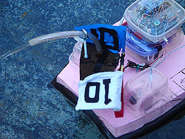
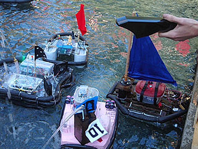
DesignThe following images depict the boat and helm subsystems. Our ship was modeled using a basic catamaran design and our helm was inspired by the “oh so cool [in theory]” Nintendo Power Glove. Craft Pictures


Helm Pictures


Drive TrainThe water propulsion system was made from Graupner 3-blade propellers and 4mm diameter marine prop shafts. The shafts connected to spider couplers which were attached to the Maxon motors on the other end. RudderThe other mechanical design element essential to water craft navigation was the rudder. The rudder was connected to a servo motor by means of a pushpin. Boat steering was accomplished by sending the servo different duty cycles which corresponded to center or shifted the rudder clockwise or counter-clockwise. FrameThe main body of the boat was made of pink extruded polystyrene foam. The team used a basic catamaran design. The basic shape was formed by stacking sheets of foam together and sanding down the foam to the desired shape. The flag and pump tower was designed in SolidWorks and cut out with a LaserCAMM. ActuationOverview: The drivetrain is a simple design comprised of two 3-blade propellers on the starboard (right) and port (left) sides of the boat. Each propeller is coupled to a long rotating shaft that allows the driving motors to be housed safely on the topside of the boat towards the bow (front). This means that the axis of the propellers forms approximately 30° angle with the surface of the water. HardwareEach propeller is independently controlled by the Maxon motors our team scavenged from the free motor bin in the TA shop. Spider couplings (M4 to M2) are used to attach the motors to the marine prop shafts, which screwed into the propellers. The propeller shafts are fed through the body of the boat; while a custom foam-core assembly both angles and houses the motors on the topside of the vessel. Our teams has used the TLE-5206 h-bridge “kits” to control the propeller motors. The motors are powered from two unregulated 7V NiCAD batteries (in parallel). The team implemented drive brake motor control and independently controlled each motor in software. Rudder Drive MotorOverview: Our team implemented the use of a rudder in addition to differential motor control to steer our vessel. We used a pushrod to connect the rudder to a servo motor. The core strategic part of our robot design was a rotating turret which housed a mechanical tape measure (Thank you Black and Decker!). Upon reaching the ball dispenser, the turret would rotate to align with Goal 3 and actuate the tape measure. A reflective sensor mounted below the mouth of the tape measure would sense when the tape was extended the correct distance. The ‘bot would then begin requesting balls which would then funnel into the turret and gracefully roll into Goal 3. HardwareThe rudder had a shaft that extended through the body of the boat. On the topside of the boat, a pushpin was used to link the rudder to a servo motor. The rudder rotated based on the provided pulse width (or duty cycle) sent to the servo. The ability of the rudder to turn the boat by itself was not as effective as we would have liked. This is probably because our rudder was not inline with the water coming from the propellers. A more effective method would have been to either use one propeller along the center axis of the boat, which would have been positioned in-front of the rudder, or to use two boat rudders behind each of our propellers. |